DOT Tires and Rims on a Motoped

TL;DR –

Front –

  • Sapim Leader 12G Spokes 16×223/16x224mm – $17.60
  • DT Swiss Onyx 32H 20mm Thru Axle 6 Bolt Disc Front Hub – $36
  • Moose Racing H 19×1.85 32H DOT (0210-0197) – $119
  • Shinko 244 2.75-19 – $35.88

Rear –

  • Sapim Leader 12G 36x206mm Spokes – $26.40
  • Pirate Cycles Universal Hub (included a front, not used) – $250
  • Moose Racing K 18×2.15 36H DOT (0210-0203) – $119
  • Shinko 244 3.50-18 – $46.88

Misc –

  • Washers (McMaster) – No. 8 Regular 0.188″ ID 0.500″ OD 92217A435 – $9.34×3 $28.03
  • Sapim Leader 16mm Nipples – $24.00
  • Misc Tube’s/Rim Strips – $25

I can’t link direct to the product on most of the above because I purchased on eBay, but here are the link’s to the seller’s I dealt with who had good prices and fast shipping

Total cost, if you use the Hub’s that came with your bike (why I didn’t is explained below) is –

  • $441.79

And if you have some time on your hand’s and don’t mind poor quality writing –

DOT wheel’s on the Motoped

(Work in progress as I upload more photo’s and notice mistakes etc)

This is my Motoped right now. The bike, like this post is also somewhat a work in progress, but other than some small stuff I want to change I’m perfectly happy with it… Except the MTB tires.

Issue’s I have with them in order of importance (to me)

  • Rapid wear (rear tire, front lasts just fine)
  • Limited choice of 24″ tires
  • Sinking into Sand
  • Flats
  • Concern about failure due to higher speed and weight of Motoped Vs MTB

First of all – I’m not a wheel builder. The rear wheel for this Motoped was the first and last wheel that I’ve ever built. I have an original pre-Kickstarter frame kit I bought from Cam in 2010. The kit came with a 48h hub (h=hole, number of spoke holes) and I laced it to a Sun-Ringle BFG BMX rim. I’ve never had an issue with it in the 5+ year’s I’ve had the Motoped, but I made mistake’s such as the spokes being a little too long and the drive side’s outer spokes weren’t trailing (I’ll post links later for what that actually means).

I have a 48 hole hub and inexpensive rim’s generally come in 32 or 36 hole. I’d rather not custom order a 48h rim or modify my probably unable to replace original hub. Motoped sell the current version hub’s for $139, but are out of stock. Luckily Pirate Cycles offer an aftermarket hub that as far as I can tell has the same dimension’s

Here it is after I drilled out the holes to 2.8mm and added a countersink.

I drilled because the spokes I’m using (12G Sapim Leader) went through from the outside fine, but getting them through from the inside was much too tight due to the insertion angle causing the threads to catch on the side, only removed 0.02mm. The countersink was because the shoulder width on my spokes required one to seat properly – the Hub’s Flange’s are probably much wider than what people would generally use 12G spokes with. Just used another larger drill bit for that as my countersink bit is pretty wide and the Disc rotor and sprocket mount’s got in the way.

I’d recommend just waiting till you order spokes before modifying any hub’s – You might not need to do what I did.

The rims I’m using are from Moose Racing, as far as I’m aware they are just generic Chinese rims with Moose Racing printed on the side. They cost $119.95 each on eBay, I’ve seen people on facebook using one’s for $39, but I couldn’t find any.

Spokes as mentioned above are Sapim Leader, 12G with 16mm long Brass Nipples.

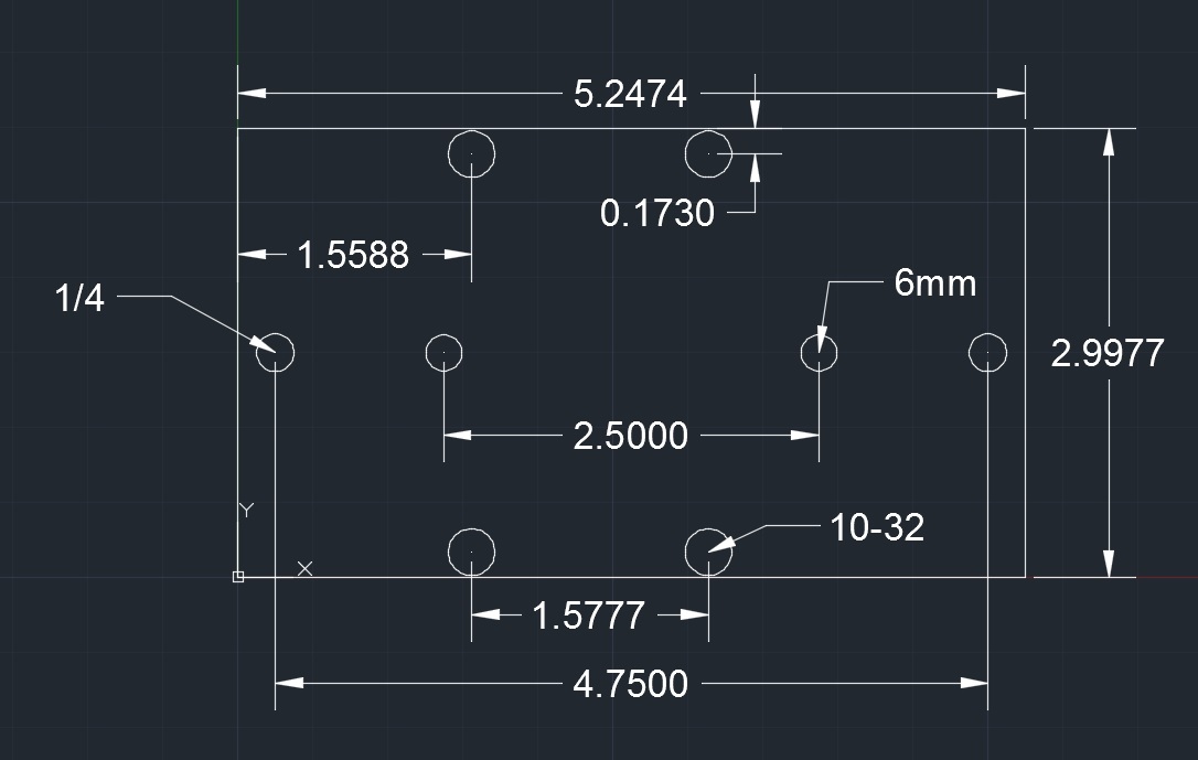
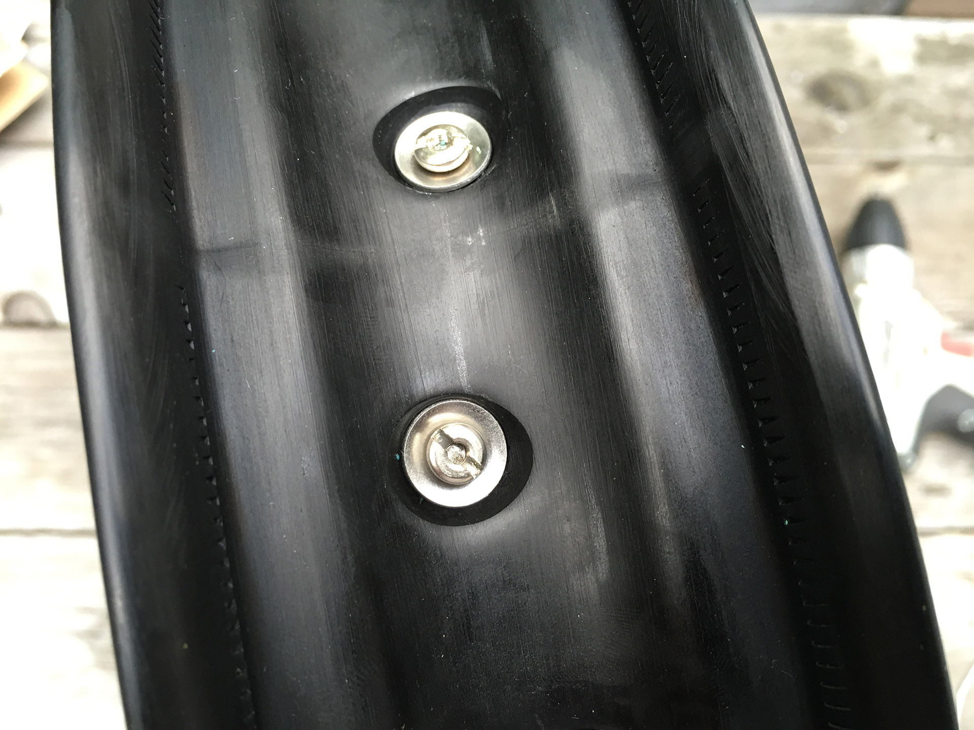
Because the Rim’s are designed for much larger Nipple’s I had to use washer’s under the head of the nipple. To stop them sliding around you need to “cup” them. I used a block of Aluminum with a blind hole drilled with a 1/2″ drill bit (because I’m using 1/2″ washers).

I just place the washer in the hole, use a punch and hammer and give it a tap, the bottom of the hole gives me a stop so the washer’s are all consistent.

Some examples of a finished washer in the hole after being struck, a stock washer, bottom and top of a finished washer.

Washer and Nipple

Washer on Nipple…

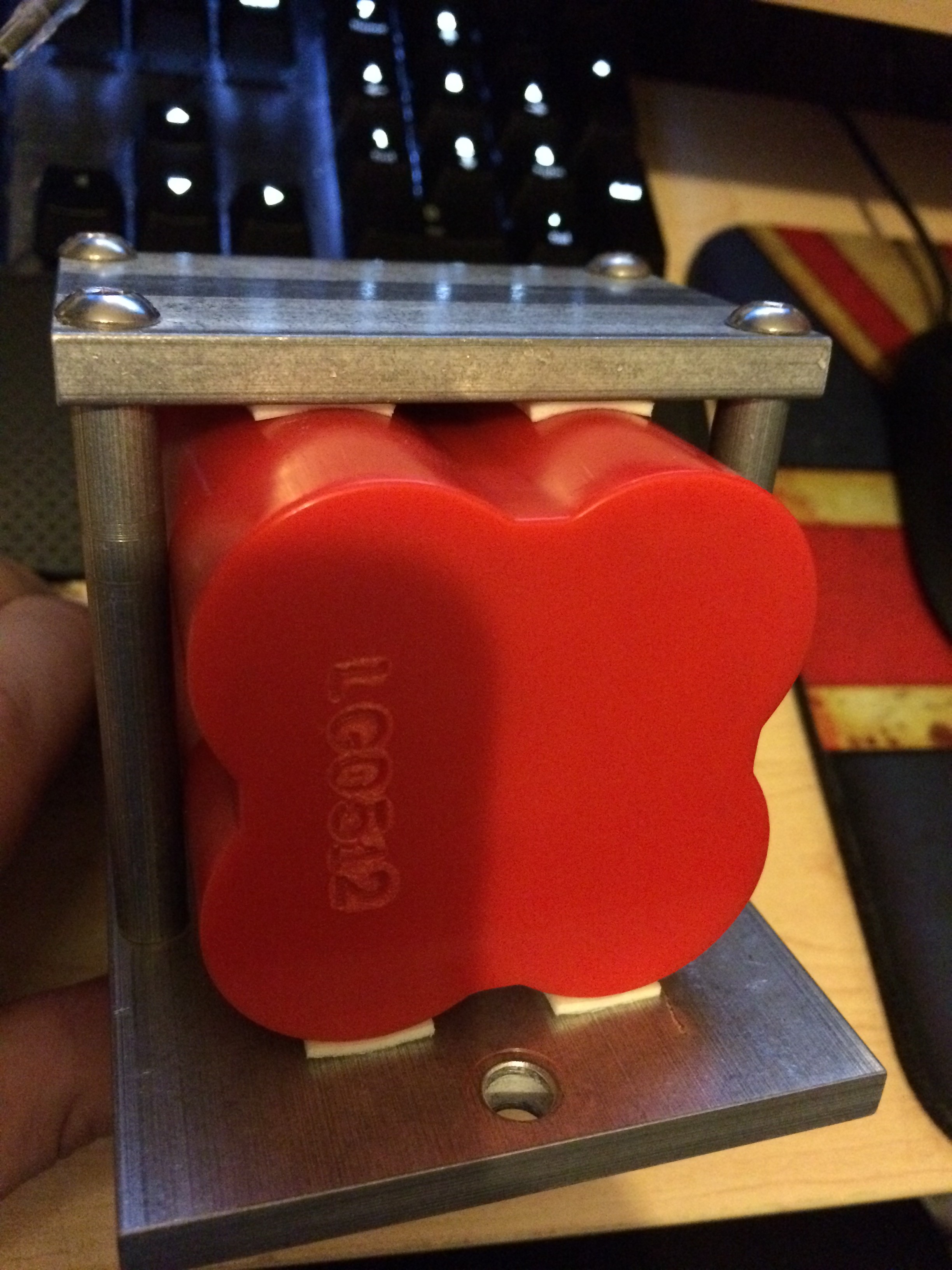
To measure the Hub I used caliper’s and just measured the dimensions needed. To measure the Effective Rim Diameter (ERD) I followed these directions which I will not bother repeating here.

http://miketechinfo.com/ERD-measuring.htm

That gave me the following measurement’s which I entered into “edd” to give me the following results

Rear –

Front –

I went with 206mm for the rear wheel and 224mm/225mm for the front (the wheel is “dished” so requires two different length’s of spoke).

All the part’s and tool’s I used –

  • Blue Park Tool Spoke Wrench (0.156 in)
  • Rock N Roll Nipple Cream
  • Rim
  • Power Screwdriver
  • Washer’s
  • Nipples
  • Spokes
  • Hub

I’m going to lace this so that the Trailing spoke’s are outer spokes on the drive side, inner spokes on the brake side. This is supposed to be stronger (the spoke’s undergoing tension during braking/power are on the outside on that side of the wheel).

I start by doing inner spokes on each side first because you won’t be able to pass the last 9 inner spoke’s through all the others if you did it that way (I learned hard way). You might be able to on a bicycle, but not with this.

This is what I mean by inner spokes, they go IN to the hub from the outside.

Just line them up with the hole in the rim that’s angled the right way (I don’t have to worry about lining up the hub’s label with the valve stem hole because my hub doesn’t have a label). Don’t tighten up the nipple’s yet, it makes it easier to lace if there’s some play.

Then when the other side is done it look’s like this – imagine trying to pass more inner spokes through that web, that’s why I did it this way, and why I had to rebuild this wheel a “couple” time’s.

The wheel uses a 3 cross “Over, Over, Under” pattern, (from the hub, the outer spokes pass over 1st, over the 2nd and then under the 3rd inner spoke)

When you’re lacing the first outer spokes it’s not too hard passing the spoke under the 3rd spoke.

One the other wide it’s a little tougher getting the spoke’s under that last cross, you’ll have to bend the spoke a little. Try to bend it over the full length of the spoke into a curve, that way it should spring back into shape. If you try to bend just the tip, it will probably want to stay that way.

I went around the rim tightening each nipple with the power screwdriver until the threads on the spoke were covered by the nipple. Then I marked one spoke with tape so I knew where I started and went around turning each nipple a 1/4 turn for a few rotation’s until they felt like they were nearly tight enough.

At that point I put it on a wheel stand.

49 Truing Stand

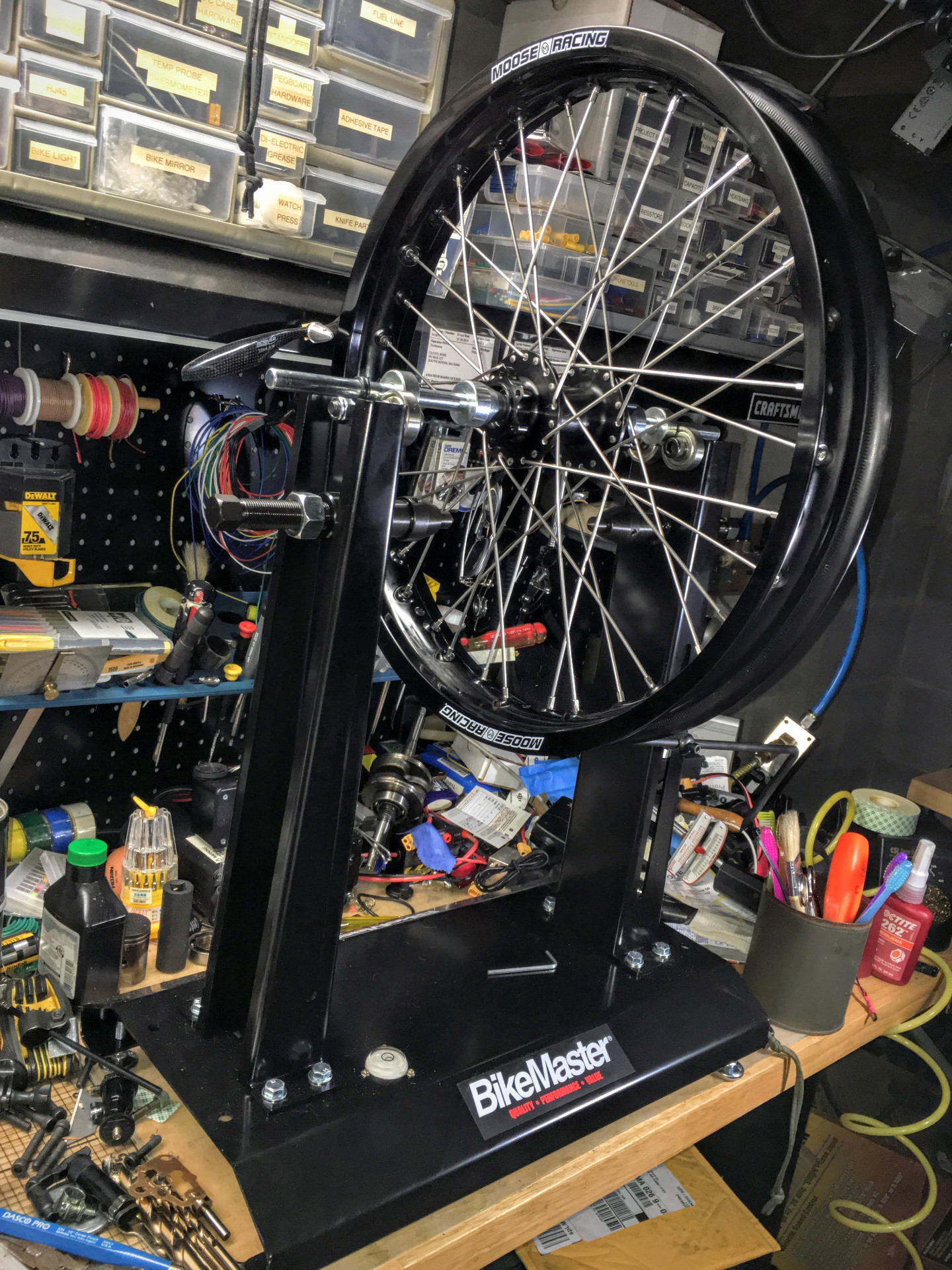
This is a BikeMaster Balancing/Truing stand. The truing part wouldn’t fit the hub, so I just put it on the balancing part at the top to true it. Line up the pointer with the bottom corner of the rim and tighten each nipple a fraction of a turn.Some got a little more, some a little less depending on how close to the rim the pointer got until it was reasonably trued.

Hopefully if you sized the spokes properly they will be just at the base of the screwdriver slot

17 Nipple After Tensioning

Lacing the front wheel was similar, just less spokes (36) and because there’s no drive side forces to worry about, both sides had the inner spokes as trailing spokes to account for forces when braking so it looked like this after all the inner spokes where done instead of being crossed over like the rear wheel.

19 Front Wheel Leading Spokes

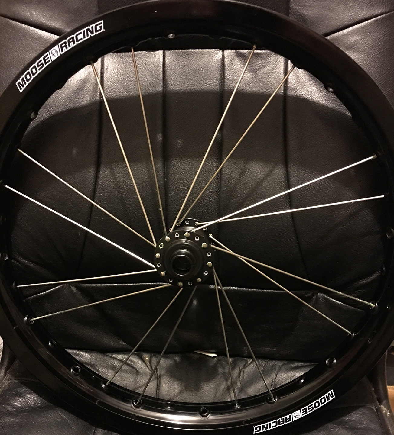
My front hub, unlike the rear has a label and everyone say’s to be “pro” you have to lace it so the label is centered when you look through the valve stem hole. I just guessed where it might be once I rotated the hub and got lucky.

20 Front view through Valve Hole

Everything else is the same as for the rear.

Mounting the MX tire’s is a little bit harder than mounting bicycle tires. I had the following tools handy from mounting tubeless tires on a Honda Z50.

41 Stuf

  • Core Tools CT122 Tire Iron/Spoon
  • Core Tools CT106 Rim Protector
  • Motion Pro 08-0471 Bead Buddy II
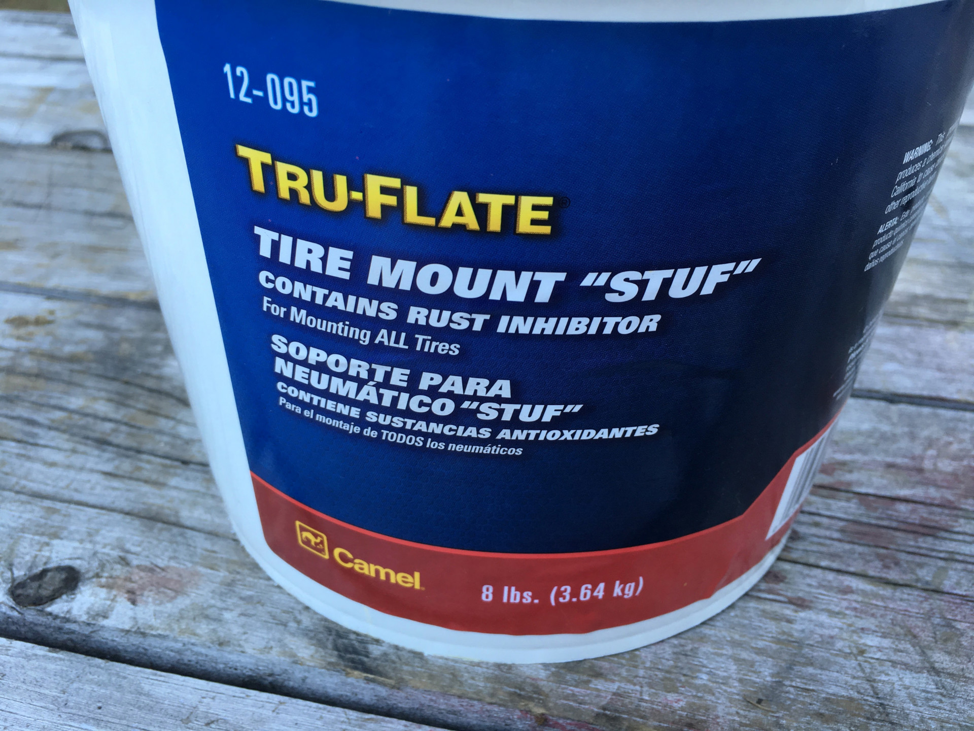
  • Camel Tire 12095 Tire Mount Lubricant

The Lubricant and the Bead Buddy (I used 2) came in handy, I don’t really think the Tire Iron’s and therefore the Rim Protector were necessary.

Also need rim strip to protect the tube from the spokes/nipples, the tire, rim etc

Rim strip just wraps around rim

Then lather on the Mounting Lube (also know as tire soap if you want to try and source it locally) to the tire and rim where they are going to come into contact during mounting.

I put it on more liberally than it looks in the photo below, just bad contrast on black rim.

The first side of the tire went on easily just using my hands by pushing the rim into one side then down onto the tire.

Then I passed the inner tube into the tire and lined up the valve, adding one of the nut’s (came with two, I read to leave the washer then a nut on the inside) to the outside to keep it in place.

Partially inflated the tube

Then the (slightly) more difficult part comes, getting the other side in. Once I got part of the bead inside the rim I put a Bead Buddy on there to 1, stop it jumping back out and 2, push the bead into the recess of the rim so I have more wiggle room when trying to get the opposite side on.

Then as I get more of the bead inside the rim add another bead buddy to keep things where they ought to be.

Moving the bead buddy as I get more of the tire mounted.

I didn’t need to use a tire iron, I just applied a little extra mounting lube and used my foot to set the tire.

And done.

I put the front tire on without the bead buddy’s, and it wouldn’t be too hard to do the rear with just the lube and some grunt work/feet. The lube is key though. I’ve used soapy water in the past and I find it run’s off or dries too fast and isn’t as thick and slippy – much prefer the lube. Off course, now I have several lifetimes supply of the stuff because it came in such a large container.

Both new wheels

26″ MTB with Synchros 2.35″ Point ‘N Chute 2 / Shinko 244 2.75-19

24″ Kenda 2.3″ K-RAD / Shinko 244 3.50-18

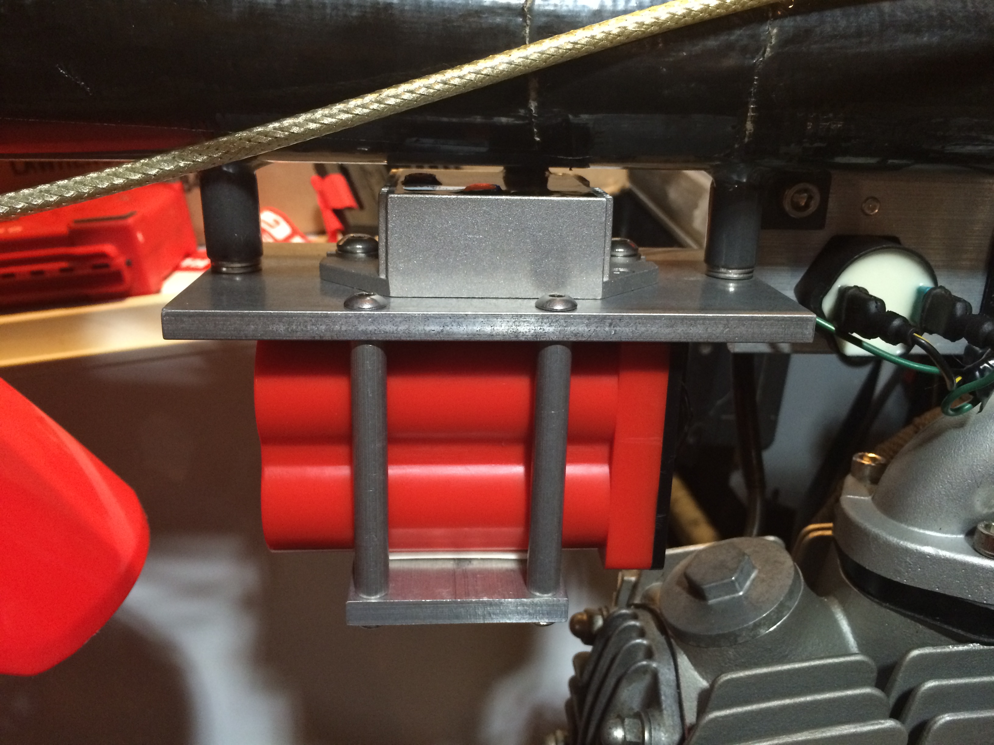
And on the bike (still need to change over Rotors and Sprocket, get new chain etc)

So the big downside is weight (which I think is worth it). These are a LOT heavier than MTB stuff.

Front MTB Wheel – 5 lbs

From DOT Wheel – 13 lbs 12 oz

Weight increase for the front of 8 lbs 12 oz

Rear MTB – 7 lbs 3.5 oz

Rear DOT – 19 lbs 9 oz

Weight increase at the rear of 12 lbs 5.5 oz

Overall the old MTB wheels weighed a total of 12 lbs 3.5 oz, the new DOT wheels weigh a total of 33 lbs 5 oz. An increase of 21 lbs 1.5 oz.

From memory my Motoped weighed around 119 lbs, so now its around 140 lbs.

Puch Magnum MkII

After seeing this Puch Magnum on Pipe Burn, I started reading up about Magnums on the Moped Army website and decided to look for one. Checked on Craigslist and saw a few that had had some modifications for over $1000 and then found a somewhat beat up, but largely untouched MkII a few hours drive away priced considerably less and picked it up on May 10th 2013.

The issues were –

  • Broken speedo
  • Broken electrical controls
  • Split seat (repaired by previous owner with duct tape)
  • Missing spoke on rear Snowflake Rim and a few others chipped
  • Loose rear wheel bearings
  • Pipe dented/random welds and not attached at rear
  • Random replacement cables
  • Rust/chipped paint on outside of tank and minor rust on hardware

If it was in excellent condition or even if the paint had been in better shape I would have left it pretty much stock, but it wasn’t – which is good as it gives me a project to make YouTube content so I picked it up and fixed the obvious issues such as the rear bearings etc.

http://youtu.be/3Px-BBBuVbs

Once I had that done I took it for a test ride to get an idea of its performance (32mph and the ZA50 two speed was running well)

http://youtu.be/yPpIN7zlsfk

Planned on repainting and inspecting every part so I did a full tear down – this is the slideshow of that, it took a couple of hours and wasn’t too bad. The right side pedal crank didn’t want to come off the shaft, I ended up (after trying for a while) just removing the left side and sliding it out. I then took an angle grinder to the crank arm to get it off later. They were bent and going to be replaced anyway.

http://youtu.be/dybSzKuyn9s

I bought new shift dampers/pucks from Atomic and sent the crank off to Moped Crank Works to get a roller bearing rod installed.

This is the video of the motors disassembly (I ended up getting an E50 engine instead so the ZA50 is still in pieces).

http://youtu.be/W_Scqsz9U5k

I’m horrible at painting, but I still wanted to do it myself.

Cleaning, Rust removal and Re-Painting of the Frame, Tank and Plastics on my 1979 Puch Magnum.

Steps I used (All materials available from Home Depot, Lowes, True Value & Ace etc – Links are to Amazon as they have more information/reviews)

  • Remove Decals with heat gun and scraper (doesn’t need much heat, but lets you remove decals in one piece and have adhesive come with it).
  • Remove any loose rust and peeling paint with a wire brush (I used a powered angle grinder for the main work, then a manual wire brush and a dremel for the tight spots).
  • Clean with neat (un-diluted) TSP (or TSP Substitute) – Do this step before the wire brush if you need to remove any dirt or oil/grease residue. The TSP de-greases/cleans and also deglosses any good paint that is left on the part to make it easier for the new coats to adhere to.
  • Rinse with water.
  • Use neat Phosphor Prep and Etch on metal parts to remove remaining rust.
  • Rinse.
  • Rustoleum “Stops Rust” Clean Metal Primer mixed 50/50 with Acetone. 1 light coat followed by another 2 to get full coverage.
  • Rustoleum “Stops Rust” Gloss Paint Mixed 75% Paint with 25% Acetone. Light coat, let flash dry then one full coat to get full coverage. Let dry for 24 hours.
  • Use Wet/Dry paper to lightly sand remove any imperfections such as dust/bugs.
  • Rinse with Water
  • Rinse with Acetone
  • Let Dry
  • Another coat
  • Repeat the above sand/rinse/coat procedure 3x
  • Touch up any spots spry gun couldn’t reach with paintbrush.

This gave me a pretty decent gloss finish without any polishing/buffing. I’m going for a Matte look (Not through choice, but because I couldn’t get it to shine…) so I’ll be using 2500 grit sandpaper to remove the few specks of dust in the finish like I did between coats and then rubbing compound to get an even finish.

I’m not happy with the finish – I will be re-doing it, probably with rattle cans as I seem to do better with that. I have vinyl decals that I bought from Raggatron on eBay, but wont be applying them until I repaint.

I used regular automotive wax and it’s protected the gas tank from gasoline just fine so I didn’t bother with a clear coat.

http://youtu.be/kaOhIAD9MCs

As I mentioned earlier, I ended up buying an E50 single speed –

I followed the directions on Moped Army and also checked with the Puch Service Manual for torque values etc.

Bearings are from Amazon. Three regular 17x40x12 and one Snap Ring version. Seals were from Treatland along with the Case Bolt kit. The Teflon E50 Clutch Cover Gasket is from Super Mopeds

Repainted the seat pan and replaced the original seat cover with one from “Miss Tammiecat~” on MopedArmy.

I sped up the painting, grinding parts etc, but the seat cover part is normal speed so its easier to see what I’m doing. First time and I could have got it a bit tighter, but the results are still excellent and I highly recommend Miss Tammiecat – Took about 4 day to receive the cover after I sent a message.

Angle Grinder to get the majority of the rust off the seat pan followed by a dremel wire brush to get in the hard to reach areas.

  • Phosphor Prep and Etch from Home Depot to clean up any remaining rust and etch the metal surface for painting.
  • Wipe down and let dry.
  • Primer coat of Rustoleum Clean Metal Primer (x2).
  • Top coat (x2) of what I happened to have laying around (The two paints are compatible, but generally just stick to the same brand as the primer).
  • Krylon High Strength Spray Adhesive (model 9090) to attach foam to the pan and then the cover to the foam. It seems to hold very well.

The edging is 6 feet of Item 8451A35, Self-Gripping Plastic Edge Trim with Metal Core from McMaster Carr, but I believe they may have sent me the textured version instead which is Item 8451A63

The edging combined with the spray adhesive seems to make the metal tabs unnecessary so I pressed them flat and did not use them at all.

Put together the Rolling Chassis, Mobil 1 Synthetic Grease and a Wire Wheel and some “Fluid Film” Rust and Corrosion Prevention spray on all nuts/bolts.

Next up was installing the Top End to the rebuilt Bottom. I owe a HUGE Thanks to Benji at Treatland for going out of his way to help me out with this.

Parts used are –

I set my ring gap at just a slight drag on a 0.007′ feeler gauge for the upper ring and slight drag on 0.009″ for the lower.

I chamfered my ports a little with a dremel to prevent the rings catching, but no case matching.

I used the Kit Install and Ring Gap Moped Army Wiki Pages to make sure those were installed properly.

Last part shows attaching exhaust studs and Kickstand with spring and finally mounting the Engine in the Frame.

Installed the Pedals onto the Cranks, the Cranks onto the Bike and then sized and installed the Drive/Pedal chains.

The cranks moved from side to side when I got the bike and had even taken a gouge out of the original ZA50’s clutch cover because of it.

I do not know if they had one originally, but I made sure the chain line matched and then made a small spacer from Acetal on my Lathe so stop any side to side play of the crankshaft.

The plastic cog on the original Pedal chain tensioner had worn teeth so I took one from a 10-speed derailleur I had laying around and used new 5mm hardware to attach it.

Using a modern throttle so I cut the old integrated throttle off the Magura lever using a Dremel and then a Mill to tidy it up.

The throttle wasnt long enough with the levers installed as far down on the handlebars as possible for the Oury Road Grips. Made a short extension from Aluminum on a Lathe to take up the empty space that would have been there.

The Mirror was $16 for two from eBay, the bar’s arent thick enough for the expanding bolt to do its job without being overly stressed and it would still be loose at the end due to the end not being tight so I made a bushing for that side.

Cable’s are a bit too long, but the throttle was the only one I have re-sized (for now). Marked and cut the right extension I needed and used a screw on cable stop for the new end.

I will be use cable ties to attach the cable housings to the frame once all the electrical is complete.

Estoril Techno Black Carbon Exhaust, which I bought based mainly on looks and price. If I was doing it again I’d get the side bleed version which offer’s better performance (It wasn’t made at the time I did this).

Came with a clear coat finish which would just burn off at the header so I stripped it and painted with “VHT Flameproof” exhaust paint. I didnt paint far enough up the header so it still burned some of the finish off, I went back and stripped the burnt varnish and added more VHT.

Mounting tab on pipe is for a Maxi frame so I needed to make a bracket. I chose to attach it at 2 points on the frame hanger so it would be a bit stiffer – Used some Vice Parallels to help make some measurements. Put those values into AutoCAD and then exported that DXF file into CamBam+ to create G-code that my G0704 Mill can understand.

One of the lower mounting bolt’s would touch the exhaust so I milled a small recess into the bracket, then cut the spacers to the correct size and tumbled them to deburr and even out the finish.

I didn’t want to use the Stock Points so I’m using a Treats Puch E-50 CDI Complete Adventure Pack – Version 2

Wired per the instructions in the above link and as directed moved the brown wire from the rear to the front and cut down the bolt so it is flush with the back of the stator plate. That stops it hitting the E-50 case preventing full rotation of the plate during timing. I added a zip tie to stop the bundle pulling the connections loose, but you don’t see that in video until I mount the stator to the engine.

I replaced most of the connections with quick connect and soldered any original connections I kept as crimps sometimes come loose/don’t have a good connection.

At this point because my aim is to just make sure the components work and the engine will run I’m connection everything as-is. Once it run’s I plan on going back and making extensions for wires that don’t quite reach, tidying up the wiring/brake cables etc.

The Olympia coil wouldn’t fit in the original coils bracket so I made a new one from aluminum (Sorry that the “making of” it takes up such a large portion of the video, I will add a link to skip it when that point starts).

I’m not using a frame ground, instead I’ll connect all grounds to the ignition coil. When I wire up the lights and any accessories they will all have a ground wire ran back to a common point – which may end up being a Terminal (“Chocolate”) Block under one of the side covers.

Fuel line is Helix Red Transparent – 3/16″ to connect the Tank to the Carb (petcock is designed for 1/4″, but will work with 3/16″ if you use a hose clamp or zip ties – All other parts in that run used 3/16″ plus makes it easier to replace without damaging the plastic tip on the petock) and 1/4″ for section that ties the two sides of the tan together.

Using regular ATF I got from a local automotive store. Fresh Gas (1 Gallon) mixed 50:1 with non synthetic 2 stroke oil (~2.6oz). Plug was gapped to .016″.

Starting just needed a little playing around with the choke and idle screw. Once I got that sorted out it now starts first kick, albeit a little rough and bogs down when given a little throttle. Next video will be setting the timing so I can test ride and tune the carb.

Checked the ignition timing (with Harbor Freight #3343) to make sure it wasn’t way off – With the Stator in the middle of its adjustment the timing starts off around 14 degree’s and with a little bit of throttle advances to 18 degree’s. I dont know enough to change from that right now so I’m going to leave it alone as thats between the Kit value and stock value from the PDF.

This is the link for the Piston Stop I used.

Starting fluid to check for leaks then a short clip of one of the break in rides. Re-checked head bolt torque and then a normal ride to check the jetting. Cylinder and Head temperatures were lower than I expected – Air temp. was about 50 degree’s. Jetting will need adjusting, once I get that figured out I will post numbers.

I’m 240lbs (as you can probably tell in the later parts of the video), bike has 16×40 gearing – max speed was 45mph, with a 30mph average over the 25 minute ride Stock 2 shoe clutch, I have blue springs and an MLM brace I will install – wanted to try stock first. No porting, rpm should be just over 8500rpm based on the Puch E50 RPM and speed chart

Timing Strip and wheel is from the Moped Army

And even though I don’t show it, I used this Break In procedure.

I’d already installed Treats CDI Adventure Pack Version 2 in earlier, but I just rigged it quickly to be able to run the Motor – No lights or anything. If this video misses anything, its probably in that or number 14 (installing the Stator/Magneto and Timing etc). This video is long enough, so I hopefully skipped or edited down anything I’ve already shown in previous ones.

I make an aluminum plate to organize the electrical bits under the side covers of the Magnum. I changed things around so the plate will be different in the video as I make adjustments (and I ended up moving from the included regulator to the full bridge rectifier of the TrailTech so the diagram has a few iterations too).

Then floating the ground on the 12V Coil and running that through a TrailTech 7004-RR150 Regulator/Rectifier with a Bat-Pac Battery Eliminator – the Regulator needs something like the Bat-Pac, Small Battery Pack or a large Capacitor to work properly – it puts out 7v at idle going to 0v at higher rpm without it. With the Bat-Pac it is around 12v at idle, goes to 14v with a little throttle and stays there through higher RPM’s.

I’m using 20W Halogens and bulb adapters for the Headlight and a “vertical fixation RED LED tail light”.

Wire’s are organized with TechFlex, zip ties etc. I do use dialectic grease on the connections (I show it only being applied to the headlight).

My remaining to-do list is just add Decals and a Black LTD front fender and when I can get a welded clutch bell, install the Hammer Clutch.

Installing a Trail Tech on my Puch Magnum, It’s a bit modern for a 35 year old bike but I liked that better than having the original speedometer plus several different gauges mounted to the bike.

Treatland sell the Trail Tech

and I got the 022-SO Basic Triple Clamp Mount with Protector from Amazon

The diagram of the part for the mount will only work with the aluminum protector, hole spacing is different if you just use the display without it.

The speed sensor needs changing, I have about 2mm of chain adjustment before the sensor would hit the rear suspension mount. I will have to remake something that attaches directly to the axle. Will be a better solution as it doesn’t require drilling and tapping of the drum brake and the wheel can be removed with the sensor still attached.

The bolt that I attach to the wheel is just a stock bolt that had a magnet epoxied to it (roughed up both surfaces), and then some heat shrink put around the outside. My camera decided to stop recording after 3 seconds of that bit so it isn’t shown.

Still do to –

  1. Install Puch Hammer Clutch
  2. Repaint
  3. Apply Decals

This is the bike as of now on 1977 Garage

Magnum 1977 Garage


https://www.youtube.com/watch?BeVJJBVA

Motoped Lighting

I often ride my Motoped after the sun goes down (I work at night) so need lights. I had been using a Magicshine 808 bicycle light with its own battery pack for a headlight and a Planet Bike Super flash for the rear. I wanted something brighter and self contained so I didn’t run out of battery power if I forgot to charge or replace batteries. So to keep the wiring as simple as possible I started out with Halogen lights and just an AC Rectifier. The headlight is a Trail Tech X2 Universal Halogen and the Regulator is the Trail Tech AC Regulator with a Trail Tech 3 Position switch/harness which takes care of a lot of the wiring.

This doesn’t need a battery and has the simplest wiring. Just black power lead from the switch to the frame ground and the red to the lighting wire from a Ricks Motorsports Lighting Stator, then connect the regulator in parallel between red and the frame ground. Plug the light into the connector on the switch harness and all done. (I didn’t get into the two lights for the diagram, that’s taken care of by the switches harness which just needs the two connections which are shown)

Unfortunately the lighting coil on the stator is unable to provide the 70 watts needed when both bulbs in the X2 are turned on. Ricks stator is rated for 90 watts, but that’s at higher RPM’s and they say to keep lighting to around 55 watts. But even with just one bulb (35 watts) I wasn’t happy with the brightness of the Halogens.

This video shows all the parts, their installation and a quick ride at night showing the light in action.

Next plan was to go to HID’s which are brighter for the same current draw. I purchased the Ballasts and Bulbs from Trail Tech to fit the X2 housing and was just going to run them one at a time (30 Watts for small top bulb and 40 Watts for Bigger lower bulb). For this I’d need to convert over to a floated ground DC lighting circuit.

The ricks stator has one lighting lead, to float the ground/use DC you need to disconnect the grounded side of the lighting coil and attach it to another wire, running it outside the case along with the original wire. I’ve done that on other stators in the past, but instead of trying it with the Ricks stator I just purchased a Baja Designs CRF50 Stator which comes with the two lighting leads and is also rated for higher power (110 Watts).

You can see the difference in the wire thickness between Ricks and Baja stators (Baja on right mounted to motor).

I had two issues with the HID’s. First is that they take a while to reach full brightness so switching between high and low I’ll have a period without much light. Second is that because they are in the same housing they point in the same direction. This wasn’t a problem with the Halogen bulbs because the low wasn’t that powerful, but the HID’s are a LOT brighter so if I aim them up for off road I’ll be blinding oncoming drivers even with only the small bulb turned on. If I aim them down then I waste a lot of light for off road illuminating the ground.

While deciding what to do I started installing a DC lighting circuit (I knew I’d need DC whether I ran HID or LED).

First I made a new mounting plate for the CDI and Coil. The CDI is aftermarket from Trail Bikes which I got in a 88cc Big Bore Kit for the Honda CRF50 engine. The Coil and Harness are stock CRF50F.

This is the CAD drawing, the Coil is mounted sideways to keep the plate as short as possible to clear the battery mounting tabs on the Motoped frame.

Motoped Plate Dimensions

Cut that out on my G0704 Mill

IMG_7544

I’m using the Trail Tech Regulator/Rectifier which needs either a Capacitor or a Battery to function properly. I have a Puch Magnum which I just used a Capacitor (4700pF), but wanted a Battery for the Motoped to keep the lights working properly at idle and to allow lighting when the engine is off. I saw someone else on the Motoped Build/Ride Facebook page had used a Ballistic Evo2 4 cell and it seemed to be a good fit and a lot lighter than the 4Ah battery I had laying around.

I made a cradle for the Battery and the Regulator which attaches to the mounting lugs on the frame

Top section which attaches to frame and mounts the Regulator.

Battery Upper

And the lower that keeps the Battery in place (has 3m double sided tape to keep it from moving).

The two plates are attached using four 0.309″ rods cut to length to take into account the battery and a layer of the 3m tape with each end threaded for 10-32 bolts.

IMG_7606

Battery 01

Battery 02

Battery 03

Battery 04

It fits the space pretty well, closer to the engine than I would have liked – but after a few rides it didn’t get warm from the engine. Tank shrouds cover it up pretty well

Battery 05

While on the Baja Designs website I noticed two LED lights – the SII and the Squadron. Running two separate lights lets me aim each one where I want. Can have one as a Low beam pointed down for the road and the other relatively parallel with the ground as High for off road. Being LED they don’t have a warm up period like the HID. As a bonus they draw a little less current, are brighter and should last longer than HID.

I decided to get those along with a Motorcycle mounting bracket that Baja sells for their Fuego lights.

This is the plate, the middle three holes are to attach to the above bracket, the outer elongated holes are for the Fuego Lights.

Fuego lights are 4″, the SII and the Squadron are smaller so I had to cut the ends off the plate and drill a couple new holes to match the lights I’m using and countersink the two holes for attaching to the bracket so the bolts didn’t stick out.

The bracket sides had to be bent inwards because its designed for a Motorcycle and the forks I’m using are much narrower. Also had to make room for a 3/8″ bolt at one end for the Squadron base bolts.

You can see the curve in the sides where I bent the bracket in the photo below.

It uses hose clamps with silicone sleeves to attach to the forks.

06

For a rear light I’m using a Universal LED Tail/Brake Light. My Motoped is registered as a Moped, which in my state doesn’t need a brake light – Just rear facing red so I don’t have a brake light switch connected to the third wire.

Cushioned 5/8″ clamp’s  attach a 1/2 Diameter by 4.15″ rod (with 1/4-20 bolts) to the sub frame and then two holes (6mm) to attach the LED and a piece of aluminum bent at a slight angle for the registration sticker.

Because I plan on running the bike with either the SII or the Squadron and not both I replaced the Trail Tech 3 Position Switch/Wiring Harness which is Off, Low, Low & High with just the plain Trail Tech 3 Position Switch which is Off, Low (Green wire), High (Yellow wire). The Blue wire is on in any position other than off so that’s used for the tail light so anytime either front light is on, so is the rear.

DC-Circuit-Motoped

Note the fuse in diagram, I used an MTC fuse holder zip tied to one of the rods on the battery cradle

The wires below will end up being wrapped in Techflex sheathing to keep it together and neater looking.

And here is the finished bike.

IMG_7639

Lights Off

Low (SII)

High (Squadron)

IMG_7637

Tail Light

IMG_7638

Some night shots of the Low on

And a short ride, taken with a GoPro Hero 3 – They don’t do so well in low light, It’s a lot brighter than it appears in the video. If you compare this to the end of the video above showing the X2 Halogen you get a good idea of how much brighter it is.


Building a new Desktop Video Editing (and Gaming) PC

My original Desktop PC for video editing was a HP Pavilion Core 2 Duo 2.4GHZ with 4GB ram and a 1GB GTX 550 Ti GPU.

Here it is getting the old 512gb card upgraded to the GTX 550

https://www.youtube.com/watch?v=f7qGAcRqL0U

When I moved over to all High Definition Cameras it started to show its age so I supplemented it with a refurbished Dell XPS 17 (l702x) laptop which I then started to use for everything. That was a HUGE improvement with a quad core i7, 12GB Ram and a GT555M 3GB GPU (GT 550 ti has a higher passmark score.

Unboxing the Dell XPS 17

https://www.youtube.com/watch?v=CGF3TBnkhqg

Even though I can edit HD video on the XPS 17 without any problems, using a desktop would be more comfortable (and I do play PC video games so an upgrade would be nice for that too).

After a lot of dickering around between going Mac with Final Cut Pro I decided to stick with PC’s as I have a lot of PC only software for CAD/CAM type stuff..

This is the package I received after copying a build I found online.

01 parts

(The above links are my Amazon affiliate links to each part on Amazon – check this PC Part Picker link to see all the components and comparison shop other stores)

I chose these because they are good performance per $ and they are all compatible with OS X if I ever wanted to install it as a “Hackintosh” build.

Motherboard

02 mobo

Anti-Static wrist band which is grounded to my heating duct-work

03 anti static strap

Intel I7 4770K

06 4770k

08 4770k

Stock cooler that came with the Processor (wont be used)

07 stock cooler

Processor being placed on the Motherboards socket

10 lowering cover

16GB of RAM

12 ram 13 ram unboxed

Being placed into sockets on motherboard – I’m using dual channel configuration (which is better, I’m not sure how exactly… ) so I followed the motherboards directions on which sockets to install them into.

14 ram installed

This is the Hyper 212 Plus cooler I’m using instead of the stock one that came with the processor.

15 cooler 16 cooler unboxed 17 cooler parts

The Backing plate goes on the reverse side of the motherboard to provide additional strength and then the X bracket secures the cooler on top of the processor.

18 backplate 20 backplate mounted 21 cooler surface

(I did add a layer of thermal paste to the above surface – check YouTube for how to do that if unsure)

22 cooler install

The fan then gets attached (you cannot get to the screws with the fan/or fans attached)

23 fan install 24 cooler done

I choose a Corsair Carbide 500R case in black because I liked its features – lots of space, nice organization, good cooling options and excellent reviews.

25 case 26 case right 27 case left

Install the I/O (In, Out) planel that came with the motherboard into the case.

28 back panel 29 panel installed

Check positioning of the Motherboard – this case didn’t require any standoff’s, and attach it with the 9 screws included with case after making sure the ports line up with the panel.

30 mobo placement


31 mobo installed

32 lineing up

33 mobo screws

34 securing mobo

35 securing mobo 2

The Graphics card I started off with in this build was a Gigabye GTX 770, thats all that I show in this post. I ended up replacing it with an EVGA GTX 780 FTW

36 gtx 770 37 gtx770 unboxed

GPU installations are just a matter of inserting it into the PCI slot and connecting the power if it needs it.

38 gpu installed

39 gpu other angle

I went with a modular supply to help keep the case a bit tidier. The Corsair TX650M got good reviews and has enough capacity to run the PC even if I make some upgrades in the future.

40 psu

41 psu unboxed

42 psu installed 43 securing psu

I bought a 120 GB Samsung 840 Evo SSD to install my OS and important files on, and I’m using a 1.5 TB HDD that I already owned for all my document folders and larger program installations.

They both simply screw onto plastic trays that came with the case and then slide right

Both sides of the finished PC, and next to my old PC – Huge difference in size, power and mess inside.

52 complete mobo side 53 complete cable side 54 compared to old pc

First boot went without a hitch into the BIOS

55 first boot

I have a licence for Windows 8 Pro and I put the installation files onto a USB thumbdrive. Installation also went fine with no issues (which surprised me).

56 os on thumbdrive 57 installing windows

Included case fan lights, Can turn them on/off using the button on the front.

58 fan lights on

Performance is excellent.

59 peformance test

Using Premiere Pro CC everything works really fast and responsively – Rendering is fast, scrubbing of clips after being imported is nice.

Games also work great, this video of Battlefield 4 game play (1080p, Ultra) was recorded using NVIDIA Shadow Play with FRAPS for the onscreen FPS count.

DIY Generator Outdoor Generator Enclosure

Home Depot was selling off the Generac GP5500 last year so I bought one. I didn’t have a Shed or a Garage to store it in so I used a Suncast GS2500 to store it in when not needed.

After a while I thought about what it would take to run the generator inside the Suncast and this is what I ended up with after looking around the internet for ideas.

http://youtu.be/3s6IcmKv8XI

The issues to overcome were getting air in to the Generators engine, getting the heat and exhaust gases out.

I found a 10″ shuttered fan by Fantech (2SHE1021) on sale, but I’d recommend something larger if you plan on doing something similar. Amazon.com has the Fantech 12″
for $117 (cheaper than the 10″).

2″ Attic Vents (SKU # 388719) were mounted in the shed wall where the Generators Air Filter was located and I put the Fantech on the opposite side.

To get the exhaust routed to the outside I used various pieces from the HVAC Aisle (Item numbers are for Home Depot).

generator vent

Speedi-Products 4 in. Round Galvanized Wall Vent with Spring Return Damper
Model # SM-RWVD 4 Internet # 202907283

(Photo is of an Aluminun one)

generator insulation

Frost King 3 in. x 25 ft. Foil Backed Fiberglass Pipe Wrap Insulation
Model # SP42X/16 Internet # 20226232 Store SKU # 710539

generator duct

Deflect-o 8 ft. Semi-Rigid Duct
Model # A038/16 Store SKU # 185868

generator cap

Master Flow 3 in. Round Duct Cap
Model # DC3 Internet # 100197348 Store SKU # 259913 Store SO SKU # 755578

The Magnet in the video below is 5685K33 from McMaster Carr.

http://www.youtube.com/watch?v=TbXiElx5J5s

To monitor the internal temperature I use a themometer from WalMart, its meant to display the outside and inside temperature but has a wireless remote sensor which I put inside the housing and can see the temperature on the Display in my House.

I also added a high temperature cut off to the built in low out cut off. That way if the fan stops working the temperature will increase but once it gets to the activation temperature of the Normally Open switch I purchased from eBay it will short the ignition coil to ground which cuts the engine. I have mine set to 50 Celcius, but comments on my video suggest I should go higher.

http://www.youtube.com/watch?v=KSTIbvAZlu0

Homann Designs MP-03 Pendant Kit

CNC Pendant from Homann Designs to control my G0704 Milling Machine. I narrowed my choices down to the Vista CNC P4-SE and the Homann MP-03, in the end I went with the MP-03 because I thought it would make an interesting project to complete.

Box with all the parts arrived within a few days from Australia to the US.

http://youtu.be/JAB76ndN75U

The kit went together more easily than I expected. I used solid core 22awg wire for the runs between components so I could bend them into the shape I wanted and stranded for the data and other wires that would need to bend when the two sides were assembled.

I used different color wire to help differentiate and troubleshoot later if necessary

  • Red: + DC
  • Green: Ground
  • White: LED Data
  • Yellow: Switch Data

mp03 inside

mp03 inside top

mp03 inside bottom


http://youtu.be/LL7y8VFgxTE

The Serial cable terminates in a Male DB9 and goes to a dual DB9 plate on my CNC Controller. There the E-Stop and Power Cables are attached inside the controller and the Serial TX/RX and ground are passed through via a DB9 Female to the PC.

How the DB9 on the end of the MP-03 is wired –

mp03 serial

Which goes to the back of my CNC Controllermp03 cables

Where it’s separated into Power, E-Stop and the Serial TX/RX & ground go back out via another DB9 to the PC running Mach3.

mp03 controller wiring


My Serial is COM8 and the 6 is set by the MODIO. Once I had that set and went through the process outlined in the Plugin’s help file I just had to set the values for the Left and Right 12 position switches who are shown in the MP-03 screen. I just went roughly 20 either side of the value when entering them into the plugin config.

Video showing the Software setup and a demo of the basic functions.

http://youtu.be/zryGXszhjXs

mp03 finished

mp03 angle

Grizzly G0704 CNC

Having followed www.hossmachine.info since I first got my X2 Mini Mill in 2008 I was very envious when he purchased an RF-45 Clone… Way too large for my shop, but I soon picked up when he announced the G0704, a BF-20 style Mill.

Took a while until I was in a position to buy one, but over this past summer I sold my X2 to a nice Gentleman who was going to use it for engraving serial numbers on parts he was machining on a VMC (He didnt want to tie up the VMC doing it).

I bought the Mill at the end of this past summer and it sat until I purchased the Electronics. Using Hoss’s recommendations I went with –

I installed and configured Mach3 on my PC (a Dell Dual 2GHZ Celeron with 1GB RAM) and hooked up one stepper and driver to the C10 to test it.

Next step was to assemble all those parts in a suitable housing. I opted to use an inexpensive ATX Computer case (Rosewell brand from NewEgg for $24). It’s cheaper and larger than enclosures designed specifically for CNC so I have plenty of room for extra parts and boards line.

Next was a wait while I went through my options. I’d made my own motor mounts when I converted the X2 using plans I bought from Stirling Steele and I even bought the Hoss DVD with his plans but decided to go with BD Tools/ALM Design/Billy Stepper and Ballnut mounts to make the process go a little faster (plus his parts are many orders of magnitude better than anything I could make). I cannot speak highly enough of Billy – his customer service is amazing and the quality of the mounts is excellent.

The bearings and ballnut mounts billy makes call for 16mm Diameter with 5mm pitch Balslcrews for the X and Y (RM1605) and 20mm with 5mm pitch (RM2005) for the Z. I sent Chai from linearmotionbearings2008 an eBay message with the Ballscrew and Nut specifications I received with the mounts and soon received them in the mail.

http://www.youtube.com/watch?v=iGGThfsvkss

I took the screws apart to clean some dirt out and to count the balls (17 per circuit in the RM1605 and 20 per circuit in the RM2005). I was missing 1 ball from a RM1605 Nut, I emailed Chai again and he shipped me a package of several balls.

Other than the little bit of grinding grit everything else was fine and fit well into the 12mm bearings.

I’d already removed the Table and Column before when I broke it down as much as I could to carrying it into my basement so I was familiar with that and it went smoothly.

http://www.youtube.com/watch?v=oHoqVccW0Ag

The Y Axis installation required some grinding of the Saddle. I tried using a drill press and end mill but it didn’t work out and resorted to an angle grinder. It looks a mess but works fine. I plan on buying a new saddle and using the CNC Mill to make oiling channels in for a one shot oiling system.

http://www.youtube.com/watch?v=9qfTgmLqWQU

The X was much easier.

http://www.youtube.com/watch?v=fBsdvBsGr2M

The Z is pretty simple, but as you can see in the video there are a lot of bolts to either tighten or loosen and no easy way to do it. The 3 bolts that help hold the head onto the Column are my least favourite part of the entire project.

http://www.youtube.com/watch?v=yY4zD-XRU6I

Now its “done” …. the rest of the work begins such as adjusting gibs, checking backlash etc etc.

Note – I switched the Lovejoy couplings out and now use Oldham style, which I bought from Amazon.com. The Lovejoys have quite a bit of play in them and introduce significant backlash, the Oldhams are more expensive (which is why I went with Lovejoy at first) – But offer much better performance.

Here you can see the Ruland Oldham on the right and the Lovejoy L-50 on the left.

Oldham and Lovejoy


Links to Amazon product pages for those (3 of the Disks, and 6 of the Hub’s for a 3 axis Machine) –

Ruland OD21/33-AT Oldham Coupling Disk, Black Acetal, Bore, 1-5/16″ or 33.3mm OD

Ruland OST21-6-A Oldham Coupling Hub, Set Screw Style, Black Anodized Aluminum, .375″ Bore, 1-5/16″ OD, 1-7/8″ Length

Here are some links you may find interesting if you enjoyed post.

russtuff – Has a lot of Machining related videos and a G0704 series of videos much better than my own with excellent narration. He used the Hoss Machine plans for his, so he also gets extra credit for that.

jmillerid – Blog entry also about the Hoss plans on a G0704, his Controller has to be the best DIY I’ve seen.

Xnaron – G0704 CNC’d with the same parts as mine – some neat quadcopter stuff too.

MrBallistic31 – Another one with BD Tools mounts and a whole bunch of other machining videos.

Headphone Audio Setup

First of all, I’ll be honest – I’m the type of person who is happy with the headphones that came with my iPhone. I just planned on getting a more comfortable pair of headphones to use in my office, but ended up getting sucked into a whole different world.

After browsing around for a few weeks and trying, but failing in finding a local store that sold higher quality headphones I choose to go with Grado SR325is without being able to try them out first. I liked their look and the reviews were good (being made in NY helped too).

http://www.youtube.com/watch?v=YXHML59-CPk

While I was looking at different headphones, started to feel I should get an Amp. Immediately after that decided to go with something tube based. The Little Dot MKIII seemed perfect for what I wanted, and so far I’m more than impressed with how it preforms and love how it looks.

http://www.youtube.com/watch?v=1U1KgXNO2Uk

I was planning on using the Amp with my iPhone/iPad’s line out connection so I ordered the FiiO L9 to provide line out audio to the Amp.

http://www.youtube.com/watch?v=gZBS7rIF22k

Got a bit cumbersome using it this way so I started looking for a DAC that has an Optical input to connect to my Laptop. Opted for the then newly released Audioengine D1 as I found a return which marked down quite a bit.

http://www.youtube.com/watch?v=j1qx87ZY94k

http://www.youtube.com/watch?v=l_fROhEw5t0

This worked great with my laptop, but while it wasnt as much a hassle as connecting the FiiO and an adapter to fit my iPhone’s case it took up a lot more space on my desk having to have the laptop there.

Then while looking for a small travel router I saw that the Apple Airport Express worked with iTunes AND had an Optical Output. Seemed to be the perfect match so I ordered one

http://www.youtube.com/watch?v=wBtjK3bnnco

So now I have all my CD’s ripped into Apple Lossless Format in iTunes on my main desktop, then using either that computer or any of my iOS devices as a remote I can start music and have it sent from iTunes wirelessly to the Airport Express, which sends it via a Toslink Optical Cable to the Audio Engine D1, which in turn has RCA output to the Little Dot MkIII which goes to my Headphones.

Here’s a video that likely explains it a lot better than the above paragraph. (the Power strip and Airport Express go under the desk so the setup looks clean)

http://www.youtube.com/watch?v=55z98RXTKKU

I’ve been using this for a few months now and it’s fantastic. Have also made a small headphone stand to keep my desk tidy.

http://www.youtube.com/watch?v=PT1Rz3DHYtI

Redline Monocog 29’er

After converting an old bike I had over to Single Speed I set out to find a dedicated Single Speed 29’er

Almost went with the Nashbar 29er, but after reading a few reviews saw the ‘Cog referenced a few times as being a more sensible choice for someone planning to upgrade parts.

Went to the local dealer who didn’t have any in store, but would order one and sell it to me for MSRP. I opted to look around, found another dealer’s online blog with a new 2010 left over that they had upgraded to Tektro Disk brakes on sale. I called, reserved it and drove down the next day.

I’d already figured on the following upgrades/changes

  • Avid BB7 Disks and FR7 Levers
  • Jagwire cables
  • Framesaver
  • Niner 32T Chainring
  • Shimano BB

Also ended up swapping out the crankset with one by FSA I’d originally bought for another bike.

Dissassembly

http://www.youtube.com/watch?v=qfLSlX8dyG4

Framesaver Application

http://www.youtube.com/watch?v=pTmxkcWn-_I

Switching Chainrings on the new Crankset

http://www.youtube.com/watch?v=pz-2D8btW5o

Installing new Disc Rotors and Cog

http://www.youtube.com/watch?v=1Iyky13gAPY

Assembly

http://www.youtube.com/watch?v=LmubjzuaquE

Jagwire Cable Install

http://www.youtube.com/watch?v=VuVseVBrRM4

Finished Bike

http://www.youtube.com/watch?v=yXnaFmV4pBw

Bike turned out great. Even with the upgrades it cost less than a new stock bike. I’m now sold on Single Speed and 29’er wheels.

Video of me riding it on some local trails

http://www.youtube.com/watch?v=k_GTDBuh-h4

And more video, this time I was also messing around with different helmet mount locations

http://www.youtube.com/watch?v=jp_bhAFpSpU

The Bike stand I’m using is by RAD Cycle Products.

Single Speed Indoctrination

I had an old 2001 Specialized Rockhopper FS, my wife bought it for me and based on bad advise from a (now out of business) Local Bike Shop got a 21″ frame and urban tires. Back then I was only interested in riding trails so this wasn’t the best for that. I ended up buying another mountain bike and this one sat for a while until it was briefly reborn as a Motorized bicycle with a poor black repaint.

I got rid of the 2 stroke engine when I got a Motoped and had been reading about single speeds, did some browsing on eBay and got a used singleater chain tensioner, rear sprocket and spacer set and a niner chainring for $30…. Cheap enough to give it a try.

http://www.youtube.com/watch?v=Vv7Rebp64bE

First time I rode it I knew I was going to buy more single speeds, third time out was a 33 mile ride along the Cape Cod Rail trail and it did great for a mountain bike with 1.75″ tires and off road gearing (32/18)

http://www.youtube.com/watch?v=GRxREXVr9Nw

Ended up selling this, but only because it got me wanting a dedicated Single Speed mountain bike more my size and after the rail trail I decided a road bike would be a good idea too.